A lot of people have set up timers for their soldering irons… There’s the built-in outlet timer approach:
Almost burned my house down a couple times. Had to make this.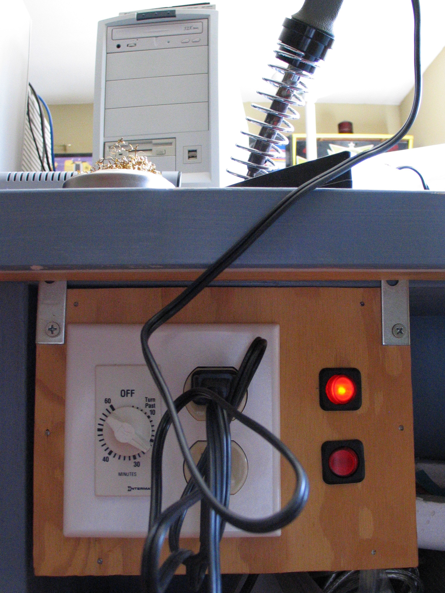
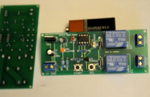
There’s the drop a relay into the power circuit approach:
The 30 Minute Soldering Iron Timer Module / DIY Electronics Kit
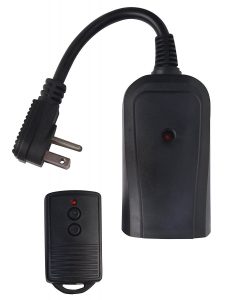
And then I came across this – the interface with a remote controlled relay approach:
Use Arduino to Interface with a Remote Controlled Power Switch
What’s interesting here is that “… to use my Arduino to interface with this power switch, all I need to do is to simulate a button press by sourcing a positive voltage to wires labeled SW1, SW2, SW3 etc.” So this is cool – RAYSHOBBY‘s goal was to use a microcontroller to control an outlet – so he modified the fob. My goal was to introduce a timer circuit to control an outlet. Let’s modify the fob!
And realized that I already had what I needed – I use one of these “Woods 32555WD” wireless remote kits to control a fan in my office at work:
And I figured I’d follow the strategy above “simulate a button press by sourcing a positive voltage to wires labeled SW1, SW2, SW3 etc.” So I took a look at the fob circuit board, noting the connections from the switches to the controlling IC, and tried to simply supply 5V from an Arduino to the ‘On’ and ‘Off’ pins. Nope.
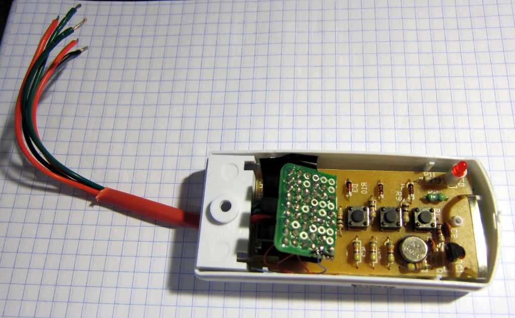
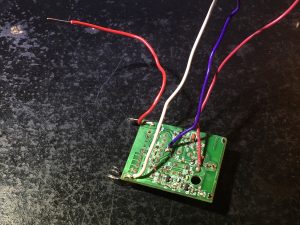
So, time to understand the fob circuit. Here’s the board:
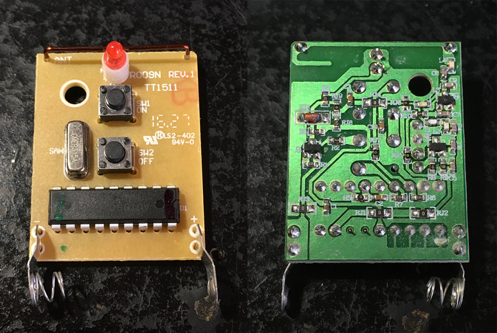
Since, generally, “I don’t know anything, what’s this?” it took a little time figure out how the circuit works. A battery supplies 12V to the circuit. The ‘on’ and ‘off’ switches are connected to pin 7 (‘on’) and pin 6 (‘off’) of the U1 IC. Power to the circuit is controlled by the transistor Q1 (at left on the right). A bunch of radio stuff is at the top right (right image).
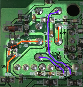
The parts of the circuit that matter for what I wanted to do are diagrammed in the two images below.
The 12V supply is at left. The pins of the two switches are at the center. The pins of the IC are at the bottom. When the both SW1 and SW2 are open (left image), the traces in blue are at GND, the traces in ‘red’* are at 12V.
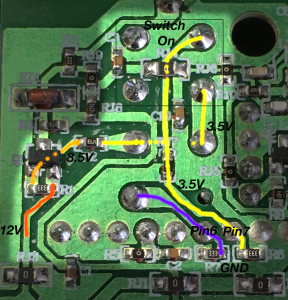
When the SW1 ‘on’ button is closed (right image), the trace in blue is at GND, the trace in ‘orange’* is at 8.5V, and the traces in ‘yellow’* are at 3.5V.
So in the case shown, pin 7 of the IC was at GND, but is momentarily pulled up to 3.5V. (And radio magic then happens to send an ‘on’ signal to the relay remote to switch power on for the device connected to it).
There are two things going on that matter, and that affect the approach I took to make this work.
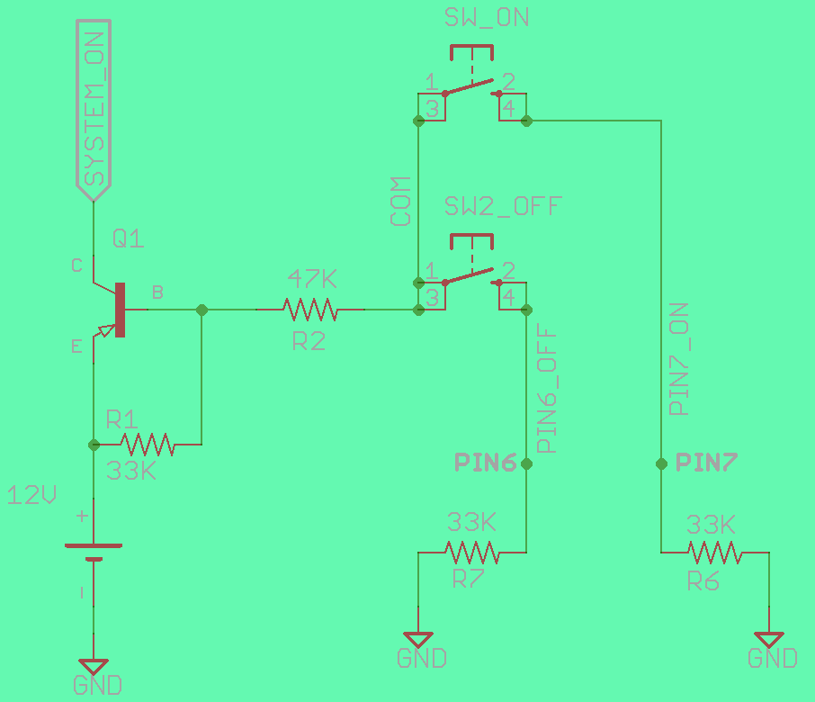
When the switches are open, R1 pulls up the base of Q1 to 12V, and net COM is held at 12V. The pins Pin6 and Pin7 of U1 are held at GND by the pulldowns R6 and R7.
When a switch is closed, a voltage divider between 12V and GND forms such that the base of Q1 goes to 8.5V, and nets COM and PIN7_ON (or PIN6_OFF) go to 3.5V. The B-E differential turns Q1 on and powers the system. So PIN7 (or, PIN6) of U1 is pulled HIGH.
What I had tried to do in my first attempt was simply to supply 5V to either PIN6 or PIN7. This doesn’t work. Why? Because the buttons tell the IC what to do (‘on’ or ‘off’), but they also turn on the whole circuit (by drawing the base voltage down and turning on the transistor Q1).
So, after figuring out what’s going on it was pretty simple to come up with a strategy – (a) Use the manual ‘on’ switch to turn the system on, and monitor the PIN7_ON net so that a timer starts with the net goes HIGH. We can use an N-MOSFET to capture that and send a signal to the board and start a timer. And (b) when the timer is done, close the connection between COM and PIN6_OFF (mimicking SW2_OFF). We can use an optocoupler inserted in parallel to SW2 for that.
Connected some wires, breadboarded it…
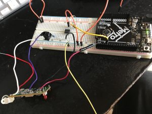
…then designed a little PCB to adapt an Arduino-based Extracore-type board (supplied by a 5V buck regulator) to start a timer and control an optocoupler to turn the switch off. Prototyped it, set up some simple code, and there you go…
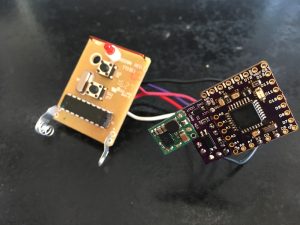
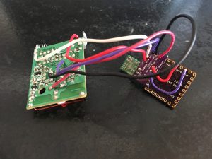
It even almost fit into the fob case, but I still had to cut the back off (and that’s why there’s a hole covered in kapton tape in the final version now).
And it actually worked… for a day or two.
I hadn’t thought much (at all) about the battery. The fob’s 12V is supplied by an A23 battery.
But an A23 battery (which is just a stack of eight 1.5V button cell batteries) only has a capacity of about 55 mAh.
An Arduino Uno will draw ~50mA when it’s running, and an ATMega328 processor without all the ‘stuff’ (pretty much what an Extracore is) will draw ~15mA. So an A23 battery could only supply my setup for a few hours, that’s it. Without careful power management, there’s no way my simple-minded idea was going to work.
There was a problem to be solved.
To be continued…
Part 1 here.
* I’m red/green color-blind
1 Comment
Soldering iron timer – part 1 – Jaldi Labs
[…] I’ll write up the logic of the fob circuit and how the board integrates with it at some point. Also will get the files up on Github (todo). To be continued… […]