Heh. Sorta.
Setup a circuit to supplement battery power on the TMP36 temperature sender. Unfortunately, I have a long way to go before I fully understand what I’m dealing with here.
- Transistors are not just trivial on/off logic switches.
- I’m trying to use a 2.2 V supply (from the solar cell array) to switch a 3 V supply (from the battery).
- Solar cells do not behave trivially, either.
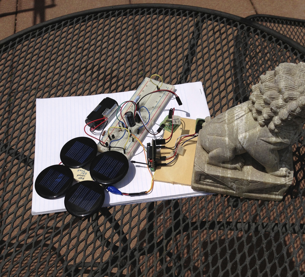
Here’s a picture of the working breadboard configuration:
Here’s the power part of the circuit – feeds a 3.3 V boost regulator that powers the TMP36 and XBee. The diagram is from iCircuit.
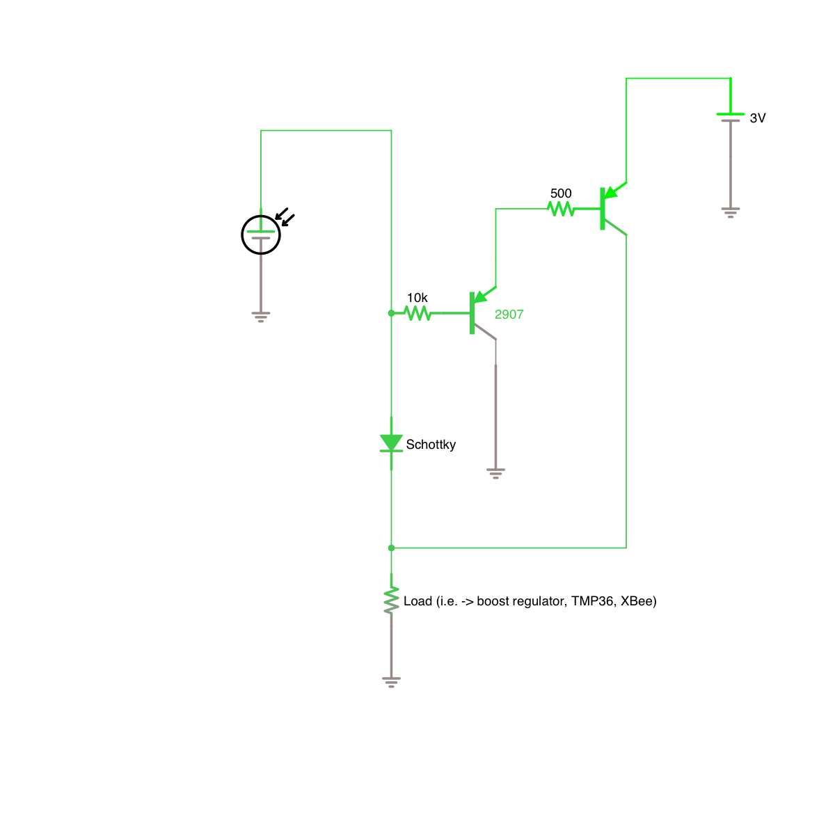
I’m certain that there are issues with this circuit that I don’t get yet. (It’s ok – that’s why you do this, to discover what you don’t know.)
The idea was that if the solar panel is supplying power, it shuts off power from the battery, and if the solar panel is not supplying power, the battery powers the circuit. The battery is not rechargeable, just a couple of typical AA’s.
The circuit works, at least in the limiting cases.
Main issue right now is the intermediate case, where PV output is somewhere between fully on and fully off, and transistor stuff I have by no means fully understood comes into play. More to come.
2 Comments
jaldilabs
Looking at the nutty data I’m getting – there’s something worse going on. My guess – the 3.3V output may be unstable given intermediate power supply behavior from the solar panel. But the 3.3 supply is the reference used to determine the temperature – if that’s going nutty, then the reported temperature is going to go nutty too… Oh boy.
Jaldi
Woof!