So, the idea was to avoid burning down the house if I forgot to switch off the soldering iron.
This was actually a very cool circuit to figure out.
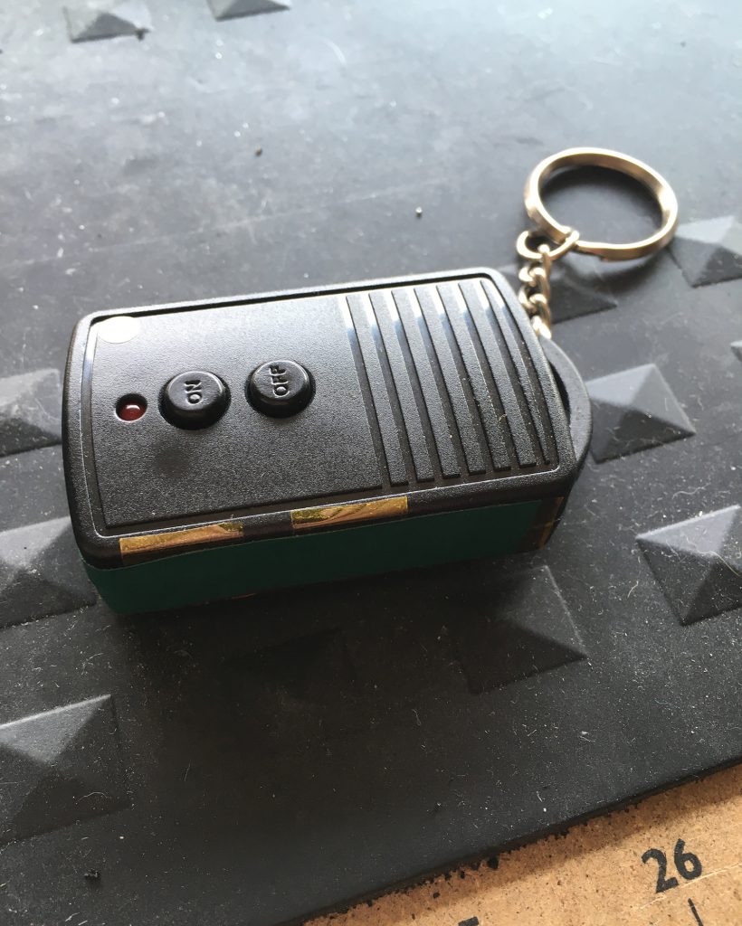
The original idea was to have the timer small enough to fit inside the fob for a wireless remote switch. But to accommodate my first idea I had to cut out the back of the fob to fit three boards – an Extracore Arduino, a buck regulator, and an optocoupler adapter. It was too big, and it used way to much power. So the hole is still there, and now it’s covered with kapton tape.
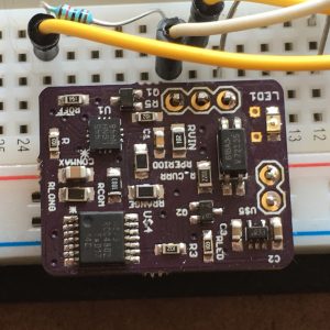
This version of the timer board is much smaller, works, and should fit completely inside the case.
Here’s the board – it’s based on a LTC2956-1 wakeup timer chip. (The LTC2956 is the little square guy near the top left.)
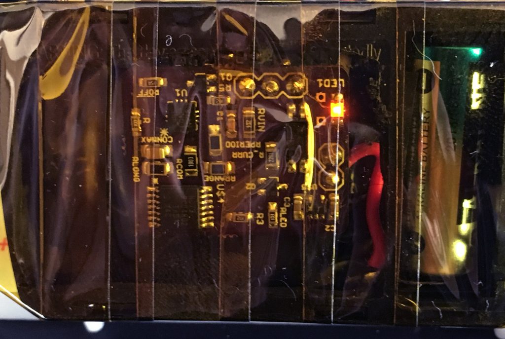
Here it is wired to the remote switch circuit. There’s an LED lit up – it’s timing!
Here’s the switch –
Power is from a 12V ‘23A‘ battery used by the fob circuit. There are basically three parts to the timer board – the LTC2956 chip which is powered by the 12V input and which is triggered by the fob ‘on’ circuit, a 74HC73 JK flipflop to handle an issue with the timer logic, and a VOS618A optocoupler to trigger the fob ‘off’ circuit. Plus a couple of MOSFETs and a voltage regulator to supply the 74HC73.
Turn it on, and 20 minutes later it powers off. Woohoo!
I’ll write up the logic of the fob circuit and how the board integrates with it in part 2. And at some point I’ll get the files up on Github.
1 Comment
Soldering Iron Timer – part 2 – Jaldi Labs
[…] Part 1 here. […]